 This is a video of our house in 2002. That was the second year for Santa flying over our house.

This is a video of our house in 2002. That was the second year for Santa flying over our house.
 This is a video of our house in 2007. I just rebuilt the mechanism. In 2005 and 2006 Santa only flew for a week or two each year. Windstorms took out the gears in the gearbox.
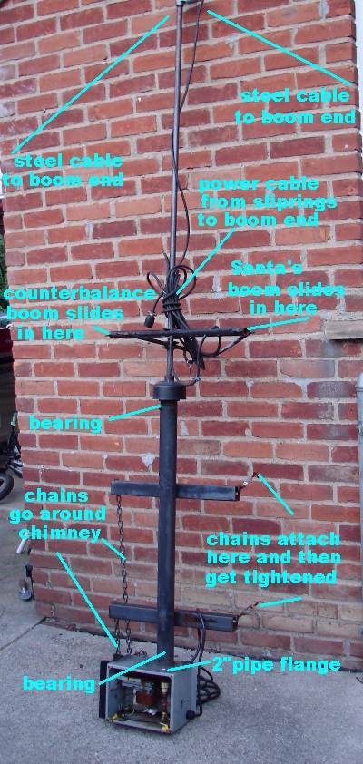 This is a picture of the old flying Santa mechanism. It has a 15' boom for Santa and a 5' boom for the counterweight. The booms are supported at their extremeties with steel cable from the topmost point on the driveshaft which is made from 1/2" steel pipe. The top fitting on the driveshaft has a power cord exiting it. Which supplies power from the slip rings to the end of the boom to light up Santa. The 2" steel pipe support tube has the chimney braces, pipe flange, bearings, and top cap/seal mounted to it. The pipe flange attaches the electrical /motor box.
 This is the magic of the whole mechanism. It is the slip ring. Here's how it works. The power comes into the brush holders. The brush holders conduct to the brushes which are spring loaded to push against the commutator (copper couplings) these are soldered to the wires that go out to the end of the boom for Santa to plug into.
Heres how its made. The end of the dirveshaft is threaded 1/2"NPT. On this is attached a 1/2" female to 1/2"CPVC adapter. This adapter has a 5" piece of CPVC pipe glued into it. The pipe has holes drilled into it for the boom wires to come out. Next to each hole a portion of a 1/2" copper "slip" coupling is epoxied. Each boom supply wire is soldered to a coupling. This completes the moving half of the slip coupling.
The other half of the slip coupling consists of an insulating bracket made from plastic. This one is HDPE plastic. Mounted to the insulating block are the brush holders. These brush holders are made from 3/4" brass flatstock and 1/4" I.D. brass tubing. The tubing is cut to allow the carbon brush spring to be compressed most of the way. Then the flatstock is cut to the same length. Next the tube is soldered to the flat stock, one on top and one on the bottom. This leaves room for the mounting holes to be drilled. The brush holders are mounted to the insulating bracket so they are seperated by a good distance to keep them from shorting out. This assembly with brushes is then mounted so the brush holders will not rub on the commmutator (copper couplings), only the brushes. Once everything is mounted, its ready to attach the power and neutral power wires.
 Inside the electrical/motor box is a Baldor 25RPM gearmotor. This has a 2" 4L V belt pulley. This drives the 1/2" steel pipe drive shaft with a 4" pulley. At the end of the driveshaft is the slipring. The main driveshaft is supported with a 1" square spherical bearing pillowblock on each end of the 2" X 2 X 1/16 support tube. One is located on the top inside the enclosure.
 This is the adjustable motor mount. On the right side is a homemade rope pulley this is welded to a 3/4 " - 10 X 5" bolt. This bolt is threaded into a 3/4" - 10 coupling nut. This nut is welded to a 1 1/4 wide hinge. This hinge then welded to a 8" T hinge. The "fitted" motor bracket is welded to the Tee hinge. This whole assembly is installed to the box. Everything had to be hand made 1 piece at a time. How it works....
 The rope pulley has a long rope down to the ground. The pulley has two halves. On one side the rope is wrapped clockwise, on the other side it is wrapped counterclockwise. This allows the threads on the 3/4" bolt to draw and push the motor mount back and forth tensioning and releasing the belt tension . I did this because of the windy weather we can get in December. When the wind blows against Santa and the belt is loose there is no wear and tear on the gearbox.
 On top of the enclosure is a bracket made from 2"X2"X1/16" square tubing. This is attached to the chimney in the center of the house. The bracket has a 3/8" thick plate at the top and bottom to support the enclosure/bottom bearing and the top bearing. The hole pattern is the same as the square pillow blocks.
 The whole assembly is attached to the chimney with chains. The chains are tightened with turnbuckles. This view shows the top bearing and the rain shield. The rain shield is made from a 4" thinwall PVC cap and a 3/4 coupling glued into the center. This is held in place with a tight fitting o-ring . This keeps the rain from running down the driveshaft and into the electrical / motor box at the bottom. Instead of attaching to the chimney a roof support pole could be added to the house, or even a large set of legs and feet could be made to sit on top of the roof. With this method It would require guy wiring to the corners of the roof or maybe even the ground.
 This is the counterweight. It is an old propane tank that has been empty for years. It has an old valve so It can't it refilled. It is a great counterweight. Some things that do not make good counterweights are :
Milk jugs filled with sand. (The sun degrades the plastic dumping slippery sand on the roof.)
Any plastic container full of water.( The freeze-thaw cycling will split the bottom , and drop a large block of ice on the roof and the awning causing everyone to drop to the floor in fear of the roof caving in.)
 This is a closeup of the spring assembly. There are two drive arms welded to the main drive shaft with a washer on top of them as a bearing surface. Then another set of arms is welded together with a washer on top and bottom. This arm setup is also reinforced with some 1/2 X 1/2 angle stock. There are some S hooks also welded to the ends of each arm. The top simply rides on top of the one that's welded to the driveshaft. It is free to swivel. Then the two screen door springs are installed between the set of driveshaft arms and the swivel arms. This allows a certain amount of wind gust to be absorbed by the springs. The swivel arm assembly is what the booms slide into. The 5' 1/2 EMT conduit boom slides into
one side. It supports the counterweight. In the other side a 15' 1/2 EMT slides into that side and supports Santa (at Christmas) or the ghost (at Halloween). The 15' piece is made up of two pieces one 5' and one 10' they are connected with an 18" piece of 1/2 SCH 80 PVC. This allows it to be taken apart easily, it's just a slip fit. These are held up at the ends with a steel cable that is attached at the top of the driveshaft and at the end of each boom.The cable attaches ith s hooks that are welded to the driveshaft and the booms. Each of the decorations both have a bolt that sticks out that slides into the end of the EMT boom. Then to keep it from falling off I attach a bungee cord to the S hook and the decoration. The power cord is then tiewrapped to the driveshaft down to the boom and then out to the decortation on the end of the boom. The decoration is then plugged into this cord.
This is a closeup of the spring assembly. There are two drive arms welded to the main drive shaft with a washer on top of them as a bearing surface. Then another set of arms is welded together with a washer on top and bottom. This arm setup is also reinforced with some 1/2 X 1/2 angle stock. There are some S hooks also welded to the ends of each arm. The top simply rides on top of the one that's welded to the driveshaft. It is free to swivel. Then the two screen door springs are installed between the set of driveshaft arms and the swivel arms. This allows a certain amount of wind gust to be absorbed by the springs. The swivel arm assembly is what the booms slide into. The 5' 1/2 EMT conduit boom slides into
one side. It supports the counterweight. In the other side a 15' 1/2 EMT slides into that side and supports Santa (at Christmas) or the ghost (at Halloween). The 15' piece is made up of two pieces one 5' and one 10' they are connected with an 18" piece of 1/2 SCH 80 PVC. This allows it to be taken apart easily, it's just a slip fit. These are held up at the ends with a steel cable that is attached at the top of the driveshaft and at the end of each boom.The cable attaches ith s hooks that are welded to the driveshaft and the booms. Each of the decorations both have a bolt that sticks out that slides into the end of the EMT boom. Then to keep it from falling off I attach a bungee cord to the S hook and the decoration. The power cord is then tiewrapped to the driveshaft down to the boom and then out to the decortation on the end of the boom. The decoration is then plugged into this cord.